Overview
SunnyCNC is a hobby CNC machine I built to run on CircuitPython/PyCNC with some ROS integration. It is a modular build: mostly 3D-printed parts, NEMA-17 steppers, and a Proxxon Micromot 50 spindle, with a Raspberry Pi 3B+ doing high-level control and an Arduino Mega 2560 plus RAMPS shield driving the motors.
Fair warning: the machine is currently torn down for a redesign. The first gantry came out far too heavy, and with a Dremel mounted it kicked back and oscillated badly enough to be useless for real cutting. I am rebuilding it lighter and stiffer.
System Architecture
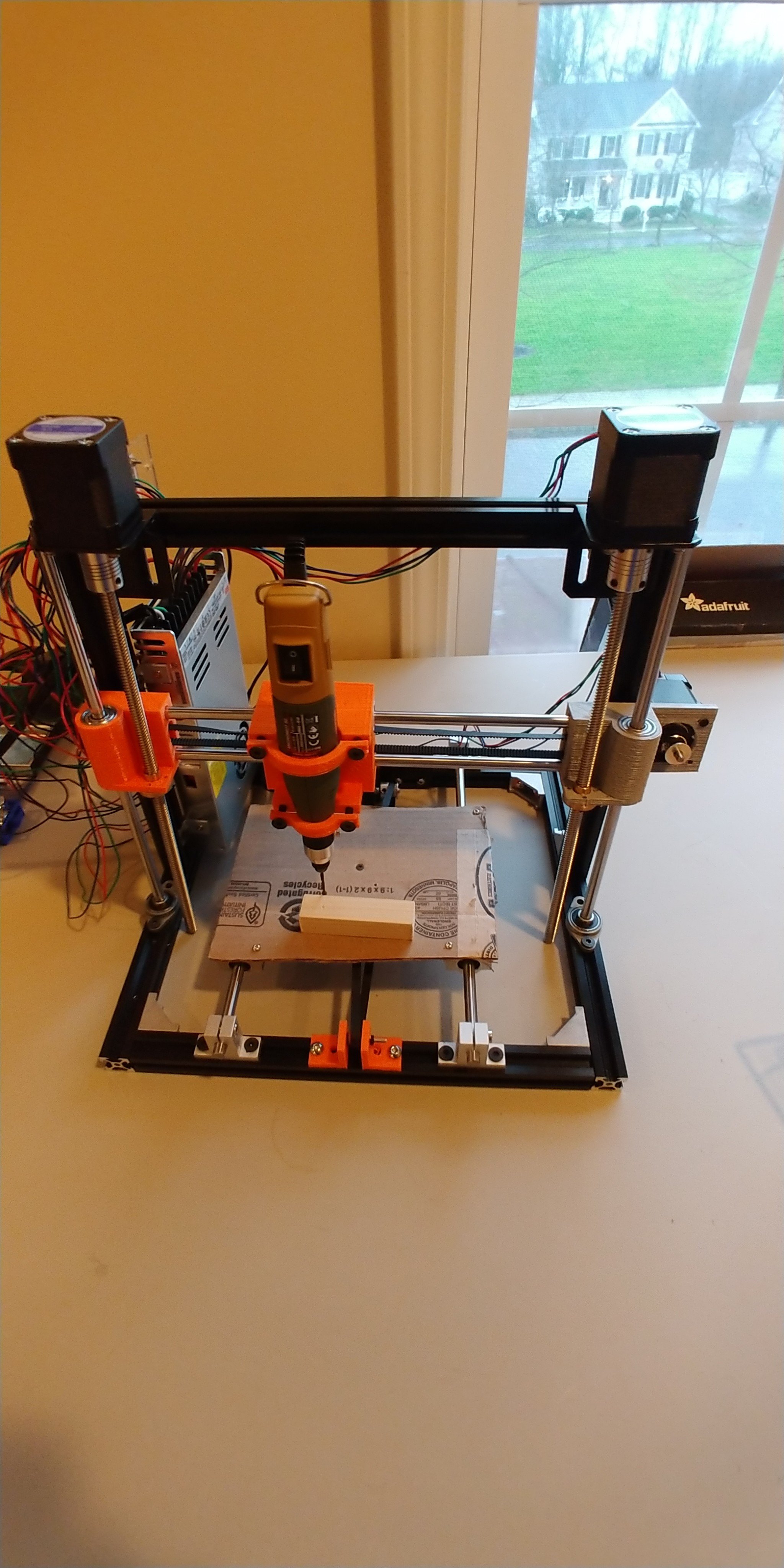
SunnyCNC machine showing the overall structure and component layout
Control is split across two boards: the Pi 3B+ handles G-code processing and high-level work, and the Arduino Mega 2560 with a RAMPS 1.4 shield does the real-time motion. The mechanics are a plain Cartesian layout:
- X-axis — dual NEMA-17 steppers driving the gantry
- Y-axis — single NEMA-17 driving the bed
- Z-axis — single NEMA-17 for vertical positioning
- Spindle — Proxxon Micromot 50 on a custom mount
- Frame — 3D-printed parts with aluminum extrusion
Components
- Raspberry Pi 3B+ and Arduino Mega 2560
- RAMPS 1.4 shield with A4988 stepper drivers
- 4x NEMA-17 stepper motors
- Proxxon Micromot 50 spindle
- Linear bearings, lead screws, and aluminum extrusion for the frame
I run a custom power distribution rather than buy the proprietary Proxxon supply:
12V Rail:
- Proxxon Micromot 50 spindle
- NEMA-17 stepper motors
- RAMPS shield electronics

5V Rail:
- Raspberry Pi 3B+
- Arduino Mega 2560
- Control electronics

Note: Custom power supply design to avoid
proprietary Proxxon power supply costs
Software
The Arduino runs a version of Marlin modified for CNC use (G-code, PWM spindle control, limit switches and an e-stop), talking over serial to the Pi. On the Pi side it is CircuitPython/PyCNC for G-code interpretation, with ROS nodes for higher-level control and OctoPrint-style web control planned but not done yet.
What went wrong
The core problem is that the gantry is too heavy. Once you have that much moving mass, everything else follows from it:
- Kickback and oscillation with the Dremel running — enough to ruin the cut and the surface finish
- Not enough frame stiffness, so it deflects under load
- 3D-printed parts that are not rigid enough for precision work
- A spindle mount that needs to be much more solid
The redesign
The rebuild is aimed squarely at the mass and stiffness problems:
- A lighter gantry in aluminum extrusion with cleaner geometry
- Linear rails instead of the basic bearings, and ball screws instead of lead screws
- A stiffer spindle mount and a counterbalance on the Z-axis
- Adaptive feed-rate control once the mechanics are sound
Files
The repo has the OpenSCAD/STL models for the custom parts (gantry, motor mounts, bearing guides, spindle holder), the modified Marlin 2.0.x firmware, and the CircuitPython control scripts and config. Current bill of materials:
Electronics:
- Raspberry Pi 3B+
- Arduino Mega 2560
- RAMPS 1.4 Shield
- 4x NEMA-17 Stepper Motors
- A4988 Stepper Drivers

Mechanical:
- Proxxon Micromot 50
- Linear Bearings
- Lead Screws
- Aluminum Extrusions
- 3D-Printed Components

Power:
- 12V Power Supply
- Custom Power Distribution